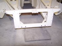
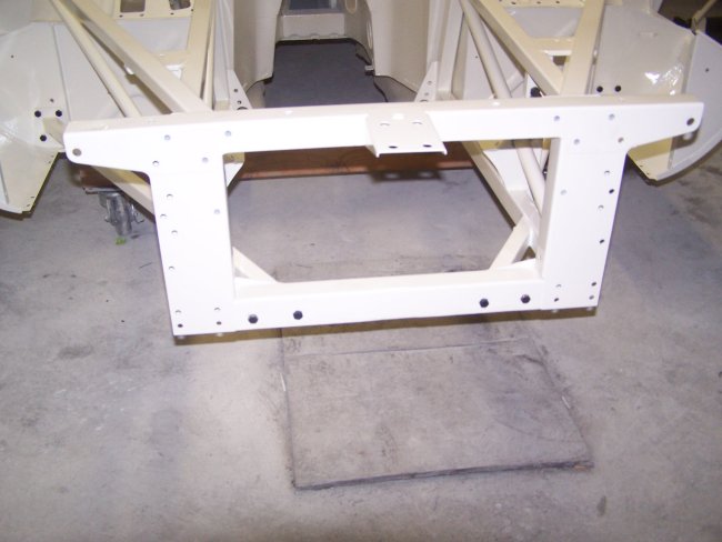
 9) The picture frame goes on next. However, there are a lot of parts that must be installed at the same time. The bonnet support, the upper wishbone
mounting brackets and the lower wishbones all have to be installed with it.
9) The picture frame goes on next. However, there are a lot of parts that must be installed at the same time. The bonnet support, the upper wishbone
mounting brackets and the lower wishbones all have to be installed with it.
|
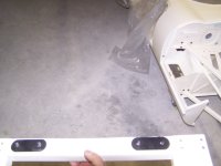 10) Only the lower center bolts and the packing plates (sheet metal spacers) should be installed on the picture from when
the frame is put in place. On this car the packing plates were originally painted/primed a semigloss black.
10) Only the lower center bolts and the packing plates (sheet metal spacers) should be installed on the picture from when
the frame is put in place. On this car the packing plates were originally painted/primed a semigloss black.
|
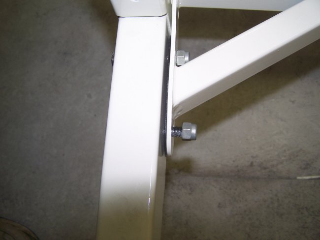
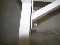 11) 5/16" Nylock nuts are used to hold all of the front end together. It's best to leave everything loose and tighten
everything as a unit, since the engine frames will need to be lined-up.
11) 5/16" Nylock nuts are used to hold all of the front end together. It's best to leave everything loose and tighten
everything as a unit, since the engine frames will need to be lined-up.
|
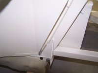
 12) The bonnet support frame should be loosely installed with just a few bolts at the top. Nylock nuts should be installed
so that the bolts don't slip out and everything drops to the floor.
12) The bonnet support frame should be loosely installed with just a few bolts at the top. Nylock nuts should be installed
so that the bolts don't slip out and everything drops to the floor.
|
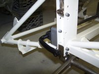
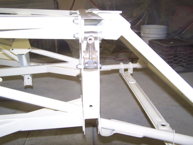
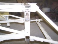 13) The upper wishbone brackets should be installed at this time. They insert into channels on the sides of the picture frame.
The bottom bolt should be left loose on each bracket since they also are used as mounting points for wiring harness hold-downs.
The center bolt hole on each bracket is for the steering rack mount, so no bolt will go in the centers at this point.
13) The upper wishbone brackets should be installed at this time. They insert into channels on the sides of the picture frame.
The bottom bolt should be left loose on each bracket since they also are used as mounting points for wiring harness hold-downs.
The center bolt hole on each bracket is for the steering rack mount, so no bolt will go in the centers at this point.
|
|
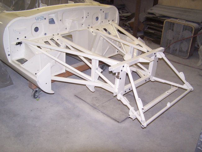
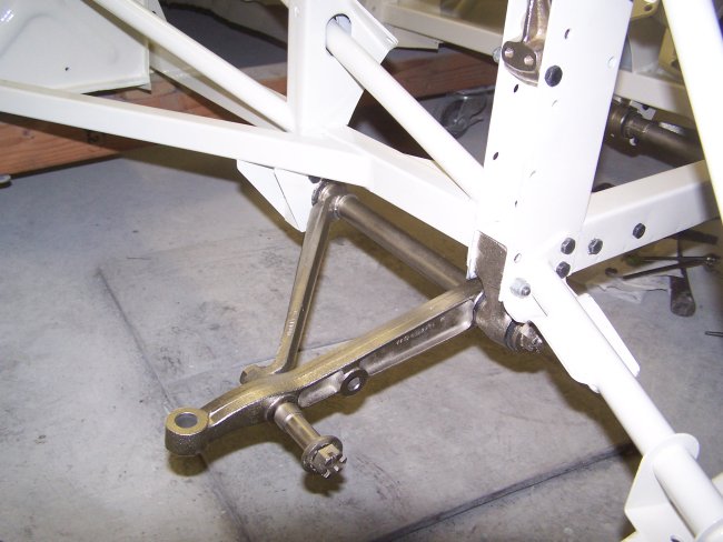
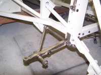 14) The lower wishbones must be fully assembled and have the pivot nuts tightened in order to fit into the frames. There are two important items
in this picture to keep in mind. The upper outboard bolts are left out, since they are the mounting points for the anti-roll bar. The bottom
outboard bolts are inserted from the back to the front, since that is the only way to get a nut onto them. At this point the inner bonnet
support bolts can be installed.
14) The lower wishbones must be fully assembled and have the pivot nuts tightened in order to fit into the frames. There are two important items
in this picture to keep in mind. The upper outboard bolts are left out, since they are the mounting points for the anti-roll bar. The bottom
outboard bolts are inserted from the back to the front, since that is the only way to get a nut onto them. At this point the inner bonnet
support bolts can be installed.
|
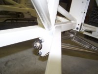 15) The rear bolts on the lower wishbones are installed from the front to back as shown in this picture.
|
 16) The Anti-Roll Bar goes on next. The bar should be centered before the bolts are tightened.
|
 17) Centering can be easily accomplished using a tape measure.
|
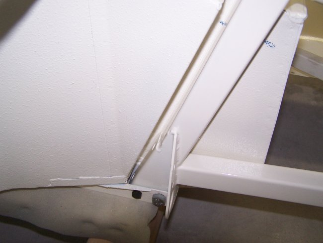
 18) At this point all of the bolts can be tighten except for the four lower bolts that attach the engine frames to
the channels in the floor, since they will need to be removed to install the reaction plate after the engine is installed.
18) At this point all of the bolts can be tighten except for the four lower bolts that attach the engine frames to
the channels in the floor, since they will need to be removed to install the reaction plate after the engine is installed.
|
|
 9) The picture frame goes on next. However, there are a lot of parts that must be installed at the same time. The bonnet support, the upper wishbone
mounting brackets and the lower wishbones all have to be installed with it.
9) The picture frame goes on next. However, there are a lot of parts that must be installed at the same time. The bonnet support, the upper wishbone
mounting brackets and the lower wishbones all have to be installed with it.
 10) Only the lower center bolts and the packing plates (sheet metal spacers) should be installed on the picture from when
the frame is put in place. On this car the packing plates were originally painted/primed a semigloss black.
10) Only the lower center bolts and the packing plates (sheet metal spacers) should be installed on the picture from when
the frame is put in place. On this car the packing plates were originally painted/primed a semigloss black.
 11) 5/16" Nylock nuts are used to hold all of the front end together. It's best to leave everything loose and tighten
everything as a unit, since the engine frames will need to be lined-up.
11) 5/16" Nylock nuts are used to hold all of the front end together. It's best to leave everything loose and tighten
everything as a unit, since the engine frames will need to be lined-up.
 12) The bonnet support frame should be loosely installed with just a few bolts at the top. Nylock nuts should be installed
so that the bolts don't slip out and everything drops to the floor.
12) The bonnet support frame should be loosely installed with just a few bolts at the top. Nylock nuts should be installed
so that the bolts don't slip out and everything drops to the floor.
 13) The upper wishbone brackets should be installed at this time. They insert into channels on the sides of the picture frame.
The bottom bolt should be left loose on each bracket since they also are used as mounting points for wiring harness hold-downs.
The center bolt hole on each bracket is for the steering rack mount, so no bolt will go in the centers at this point.
13) The upper wishbone brackets should be installed at this time. They insert into channels on the sides of the picture frame.
The bottom bolt should be left loose on each bracket since they also are used as mounting points for wiring harness hold-downs.
The center bolt hole on each bracket is for the steering rack mount, so no bolt will go in the centers at this point.
 14) The lower wishbones must be fully assembled and have the pivot nuts tightened in order to fit into the frames. There are two important items
in this picture to keep in mind. The upper outboard bolts are left out, since they are the mounting points for the anti-roll bar. The bottom
outboard bolts are inserted from the back to the front, since that is the only way to get a nut onto them. At this point the inner bonnet
support bolts can be installed.
14) The lower wishbones must be fully assembled and have the pivot nuts tightened in order to fit into the frames. There are two important items
in this picture to keep in mind. The upper outboard bolts are left out, since they are the mounting points for the anti-roll bar. The bottom
outboard bolts are inserted from the back to the front, since that is the only way to get a nut onto them. At this point the inner bonnet
support bolts can be installed. 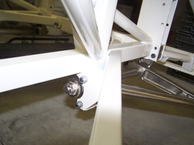 15) The rear bolts on the lower wishbones are installed from the front to back as shown in this picture.
 16) The Anti-Roll Bar goes on next. The bar should be centered before the bolts are tightened.
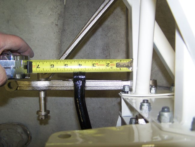 17) Centering can be easily accomplished using a tape measure.
 18) At this point all of the bolts can be tighten except for the four lower bolts that attach the engine frames to
the channels in the floor, since they will need to be removed to install the reaction plate after the engine is installed.
18) At this point all of the bolts can be tighten except for the four lower bolts that attach the engine frames to
the channels in the floor, since they will need to be removed to install the reaction plate after the engine is installed.